Chip tester
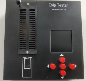
Table of contents:
Description
This integrated circuit tester is designed to test logic integrated circuits: TTL and CMOS (74, 40, and 45 series), SRAM, DRAM and EEPROM, can also test some operational amplifiers, optocouplers sensors, and more. Menus and results are displayed on a 128x160 color display.
The device is powered by the miniUSB port, through which it can also be connected to a computer. The software allows you to develop and debug tests, read the contents of ROM, start testing chips with the display of results and update the firmware.
Supported chips
At the moment, the test base has more than 300 chips and this number is growing.
Below is a list of supported logic chips
TTL, 74-series
00, 01, 02, 03, 04, 05, 06, 07, 08, 09, 10, 11, 12, 13, 14, 15, 16, 20, 21, 22, 23, 25, 26, 27,

28, 30, 31, 32, 33, 34, 37, 38, 40, 42, 46, 47, 49, 50, 51, 53, 54, 55, 64, 70, 72, 73, 74, 75, 77, 78, 80, 82, 83, 85, 86, 89, 90,

92, 93, 95, 97, 107, 109, 112, 113, 114, 125, 126, 128, 132, 134, 136, 137, 138, 139, 140, 145, 148, 150,

151, 152, 153, 154, 155, 156, 157, 158, 160, 161, 162, 163, 164, 165, 166, 168, 169, 170, 173,

174, 175, 180, 181, 183, 184, 189, 190, 191, 192, 193, 195, 198, 238, 240, 241, 242, 243, 244, 245, 247, 251,

253, 257, 258, 259, 260, 273, 279, 280, 289, 295, 298, 299, 323, 352, 353, 365, 366, 367, 368, 373,

374, 375, 377, 390, 393, 396, 452, 465, 466, 533, 534, 541, 573, 574, 595, 597, 620, 630, 640, 643, 646, 651,

652, 670, 688, 873, 874, 1000, 1002, 1003, 1004, 1005, 1008, 1010, 1011, 1020, 1032, 1034, 1035,

4035, 4520
CMOS, 40- and 45-series
4001, 4002, 4003, 4006, 4007, 4008, 4010, 4011, 4012, 4013, 4015, 4016, 4017, 4018, 4019, 4020, 4022, 4023, 4024, 4025,

4026, 4027, 4028, 4029, 4030, 4035, 4036, 4040, 4043, 4044, 4049, 4050, 4051, 4052, 4053, 4060, 4061, 4066, 4069,

4070, 4071, 4075, 4073, 4081, 4093, 4094, 40192,

4502, 4503, 4511, 4512, 4516, 4519, 4520, 4555, 4556, 40103, 40106, 40161
Intel 82- and 32-series
  8255, 8282, 8283, 8286, 8287,

  8212/3212

  8216/3216, 3226
Other logic
Am25S05 AM2507, AM2508, AM25S10

Am29705

MSD047, MSD101

DS3881

MC14194

MC14076

MC14580, MC14585, MC14554
USSR TTL, 155/531/555/1531/1533 series
AP2, AP3, AP4, AP5, AP6, AP9, AP10, AP14, AP15, AP16, AP17, AP24, AP26

ID3, ID4, ID5, ID6, ID7, ID9, ID10, ID11, ID12, ID13, ID14, ID15

IЕ1, IЕ2, IЕ4, IЕ5, IЕ6, IЕ7, IЕ8, IЕ9, IЕ10, IЕ11, IЕ12, IЕ13, IЕ14, IЕ15, IЕ16, IЕ17, IЕ18, IЕ19, IE20, IЕ23

IM1, IM2, IM3, IM5

IК1, IK2

IP2, IP3, IP4, IP5, IP6, IP7

IR1, IR8, IR9, IR10, IR11, IR12, IR13, IR15, IR16, IR17, IR18, IR19, IR21, IR22, IR23, IR24,
IR26, IR27, IR29, IR30, IR32, IR33, IR34, IR35, IR37, IR38, IR40, IR43, IR51, IR52

IV1

КP1, КP2, КP5, КP7, КP11, КP12, КP13, КP14, КP15, КP16, КP17, КP18, КP19

LA1, LA2, LA3, LA4, LA6, LA7, LA8, LA9, LA10, LA11, LA12, LA13, LA16, LA17, LA18, LA19, LA21, LA22, LA23, LA24

LЕ1, LЕ2, LЕ3, LЕ4, LЕ5, LЕ6, LЕ7, LЕ10, LЕ11

LI1, LI2, LI3, LI4, LI5, LI6, LI8, LI9, LI10

LL1, LL2, LL4

LN1, LN2, LN3, LN5, LN6, LN7, LN8, LN10

LP3, LP5, LP7, LP8, LP9, LP10, LP11, LP12, LP16, LP17

LR1, LR3, LR4, LR9, LR11, LR13

TM2, TM5, TM7, TM8, TM9, TM10

TR2

TV1, TV6, TV9, TV10, TV11, TV15

TL1, TL2, TL3
RP1

PR6, PR7

RU2, RU5, RU8, RU9

SP1
USSR CMOS, 176/561/1561 series
ID1, ID2, ID3, ID6, ID7,

IЕ1, IЕ3, IЕ4, IЕ8, IЕ9, IЕ10, IЕ11, IЕ14, IЕ16, IЕ19, IЕ20, IЕ21

IК1

IM1

IP2, IP5

IR2, IR3, IR6, IR9, IR10, IR11, IR12, IR14, IR15

КP1, КP2, KP3, КP4, KP5

КT1, КT3

LA7, LA8, LA9, LA10

LЕ5, LЕ6, LЕ10

LI1, LI2

LN1, LN2, LN3

LP2, LP4, LP11, LP12, LP13, LP14

LS2

PR1

PU3, PU4, PU7

RU2

TV1

TL1

TM1, TM2, TM3

TR2
USSR other chips
КR1561КP1,
КR580VV55

КR580IR82, КR580IR83

КR580VA86, КR580VA87

K589IR12

K589AP16, K589AP26

KР1802IR1
KR514ID1, KR514ID2

K559IP1

KR571XL4, K1102AP13
SRAM
2102A (1024 x 1)

MM2114,UM6114 (1024 x 4)

D2115A (1024 x 1)

HM6167 (16384 x 1)

61C16, 62C16 (2K x 8)

61C64, 62C64, DS2064 (8K x 8)

W24129A, AE88128AK (16K x 8)

61C256, 62C256, MCM6206CP20 (32K x 8)

61C512, 62C512 (64K x 8)

62C1024, HM628128, TC551001 (128K x 8)

6C4008 (512K x 8)

K565RU2 (1024 x 1)

K132RU4 (1024 x 1)

K537RU10 (2K x 8)

KR185RU5 (1024 x 1)
DRAM
2118 (16K x 1)
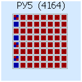
4164 (64K x 1)
41256 (256K x 1)
KM41C1000 (1M x 1)
4416 (16K x 4)
41464, 4464 (64K x 4)
514256 (256K x 4)
K565RU5 (64K x 1)
K565RU6 (16K x 1)
K565RU7 (256K x 1)
ROM (reading and checking for "cleanliness")
SN74188N (K155RE3)

K555RE4, K155RE21, K155RE22, K155RE23, K155RE24

SN74287 (556RT4),
Intel 3601, 3621 (556RT5)

82S191 (556RT7)

82S191 (556RT7), 93427С (556RT11), 82S136 (556RT12), 82S137 (556RT13), DM87S184 (556РRT4), DM87S185 (556RT15), Am27S35C (556РТ20)

27C16, 27C32, 27C64, 27C128, 27C256, 27C512, 27С1000 (27C010, 27C1001), 27С2000 (27C020, 27C2001), 27С4000 (27C040, 27C4001), 27С8000 (27C080, 27C8001)
Operational amplifiers
LM358 (LM158, LM258, LM2904)

LM393 (LM193, LM293, LM2903)

LM386

LM324 (LM124, LM224, LM2901, LM2902, TL084)
Also, the tester should work with other op-amps that have the same pinout and work from a 5V unipolar voltage source.
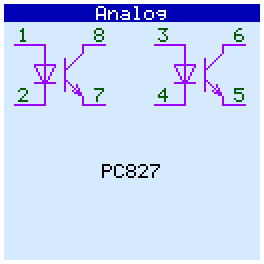
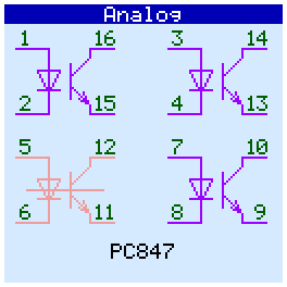
Optocouplers
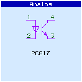
PC817, PC827, PC837, PC847,

HCP2601 (6N137, HCP2611),

4N35,

TLP504A, TLP504A-2

CN74-2, CN74-4
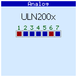
Other analog IC
ULN2003 (ULN2002, ULN2004)

ULN2803

DG4008
Sensors
DS18B20, DS18S20, DS1822
(temperature sensors)
DHT11, DHT22 (AM2301, AM2302, AM2320) (humidity and temperature sensors)
Device
The device consists of two boards. The main board contains the ZIF-socket, LCD, keyboard, microcontrollers and USB-to-UART. Additional board contains MOSFETs and control registers.
Assembled device:

User interface
Main menu
When you turn on the tester, we see the main menu:
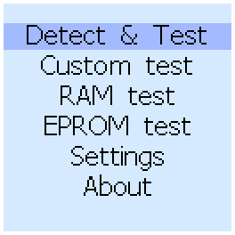
From the menu you can run an automatic test of logical- and analog-microcircuits, perform a manual test, check the SRAM, DRAM, or EPROM. You can also open Settings and see information about the firmware version and the number of tested chips in the database.
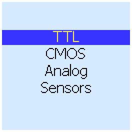
Testing chips with autodetect
To check and identify microcircuits, use the first menu item (Detect & Test). First you should choose the type of chip - CMOS (40- and 45-series), TTL (74-, 82- and 32-series ant othe logic chips), Analog(operational amplifiers, optocouplers, ULNxxxx) or Sensors(DS18xxx, DHT11)
After that, you can install the chip to the ZIF-socket:
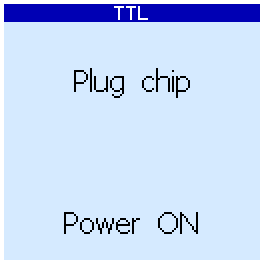
On this screen, you can press the up button to turn on Power ON, and use the down button to turn it OFF. When it is OFF (this is the recommended mode) power to the chip under test will be supplied from the microcontroller. When Power ON, the tested chip will be powered through MOSFETs, which provide more current. It makes sense to use this mode if the test with Power OFF fails.
Pressing the right or center buttons starts the test:
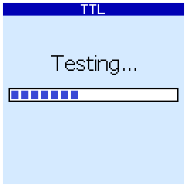
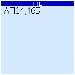
The device will iterate over all the tests in its database and show a list of chips for which the tests were successful. For example, for the 74LS465 chip, the result would be (here "АП14" its analogue from the USSR):
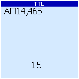
If no tests are successful, the device will restart them, but in a slower mode. Additional delays will be added between signaling the input and reading the outputs. If after this the test is successful, a number is displayed at the bottom of the screen. This number characterizes the speed of the chip (the smaller - the faster):
If this test also fails, the result will be "Unknown".
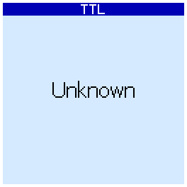
To re-check, you can click the right button.
Analog chips test
When checking analog circuits, their pinout is displayed. If the microcircuit contains several gates (operational amplifiers, optocouplers) and some of them are faulty, then they are displayed in red and crossed out:
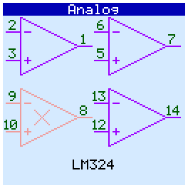
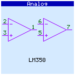
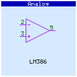
Op amps tested in comparator mode.
SRAM and DRAM testing
Before starting the memory test, a prompt appears to insert the chip into the panel and turn on / off the power. As a result of the check, the device itself will determine the type of chip installed.
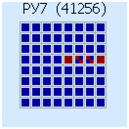
The result of the check is displayed in the form of a map. The filled cells are completely serviceable areas, crosses - the area contains bad cells. "Good" memory areas are shown by filled cells, Bad aread are shown to crosses. Test Result for DRAM 4164 (565РУ5 - analogue from the USSR):

And this is how the result looks if there are a lot of bad cells::
Another example - 41256 (565РУ7 - analogue from the USSR) with several bad cells:
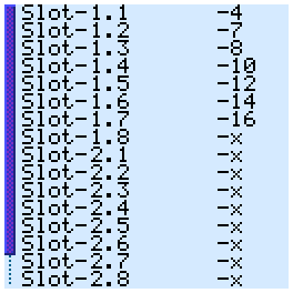
For static memory, the result screen looks like this in the case of a working chip:
In case of errors, the memory map and data bus bits on which errors are found are displayed on the screen:
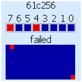
In this example, the chip has problems working with data bits 7 and 4.
EEPROM blank checking
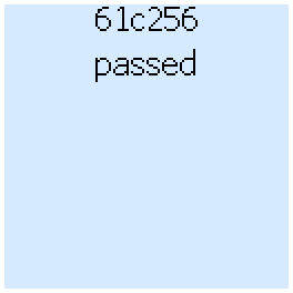
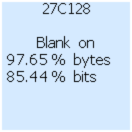
Tester can read some EEPROM chips and check if they are "blank". If the chip contains data, then the percentage of pure bits and bytes is displayed.
First, select the type of chip:
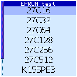
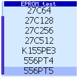
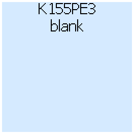
After checking, either a message is displayed that the chip is completely blank, or information about the number of recorded bits and bytes.
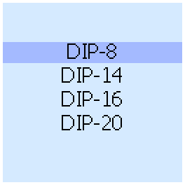
Custom test
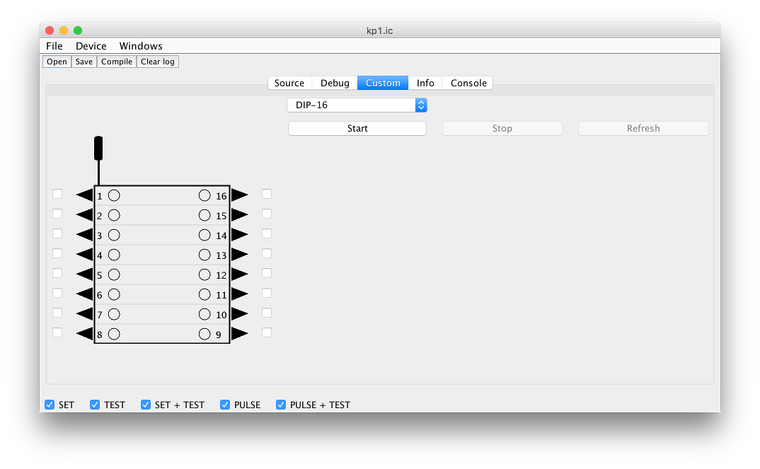
Custom test mode allows you to set the desired levels at the inputs of the chip and see the status of its outputs. First choose a case:
Manual test has two modes - "Setup" and "Output". Use the cursor buttons to move between the pins and mode names. In Setup mode, you configure the pins for input or output and configure the power of the chip. This mode has three sub-modes - "I/O", "GND" and "VCC". The outputs are drawn with the arrow FROM the chip. If the arrow is directed TO the chip, then the pin is's input, and the tester can change the level on it. In "I/O" submode, you can configure each pin as input or output.
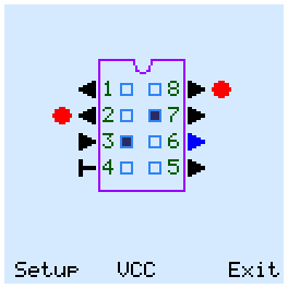
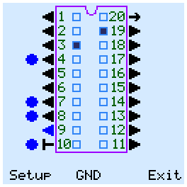
In GND submode, you can connect minus power (ground) to the chip. ZIF pins, that connected which the GND MOSFETs, are marked with a blue circles. VCC submode is similar to GND, and supplies + 5V power to the pins. ZIF pins, that connected which the VCC MOSFETs, are marked with a red circles.

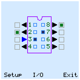
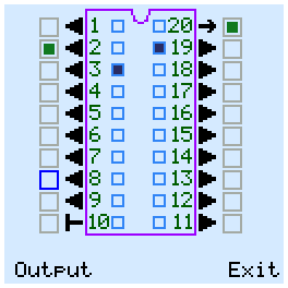
In Output mode, the tester can change the status of the inputs and outputs of the chip. The output voltage levels are displayed outside the chip package. The green square means high logic level. For input pins it means pull-up.
The status of the outputs of the chip is displayed by blue squares inside its package.
To exit to the main menu, select the "Exit" button in the lower right corner and press the center button.
Settings screen
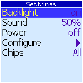
Here you can configure the automatic shutdown of the backlight by timeout. If Backlight is on, the backlight will always be on.
You can also adjust the volume of sound beeps when you press the keys and in the case of completion of tests.
Also here you can select the default value of Power before the tests.
The Configure menu item will perform a self-test and display the connection diagram of mosfets to socket pins
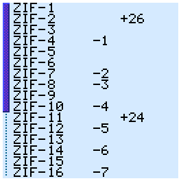
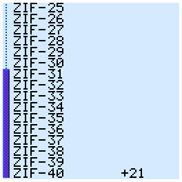
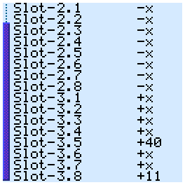
Here on the left are the numbers of MOSFETs, and on the right are the pins of the panel with which these keys are connected. In total, the device has 24 mosfets - 16 connect the ground and 8 connect the VCC.
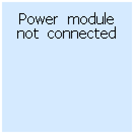
If the MOSFETs module is missing, not connected or not recognized for any reason, the tester will report this:
The Chips parameter determines which chip names will be displayed:
USSR - show only chip names according to the USSR classification
USA - show only chip names according to USA classification (Tehas Instruments, Intel)
All - show all names
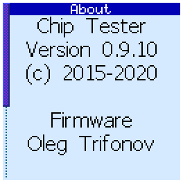
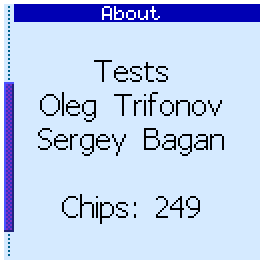
About screen
Here you can see information about the firmware version, its authors and the number of TTL and CMOS tests in the database.
Software
The tester is connected to the computer via a miniUSB cable.
Software allows
- create, compile and debug tests
- read ROM contents
- run logic chip tests
- update tester firmware
The program is written in Java and requires a Java Runtime version of at least 8. To run software use command
java -jar software.jar
First you need to initialize the device. In the main menu select -> "Device" -> "Connect to". This will display a list of detected COM ports. Among them, select the port to which the tester is connected. If successful, the connection will be established, and the port name will be remembered, a command to connect to this (last successful) port will appear in the Device menu. When connected, the program will check for firmware updates on the server and offer to update if it finds a new version.
Menu command Device -> "Device info" displays the device information window. Here you can see the firmware version, make a backup copy of the firmware and update it (buttons "Read firmwre" and "Write firmware", respectively).

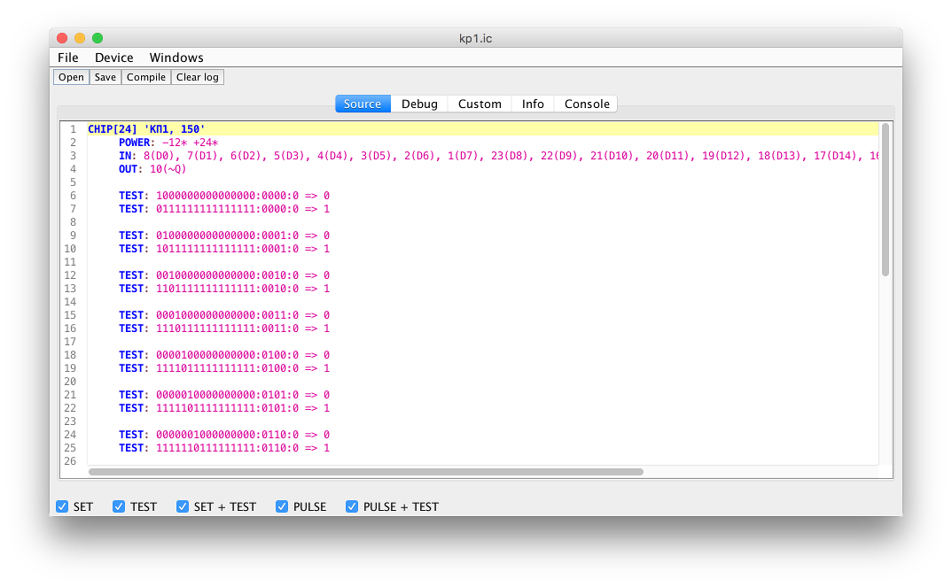
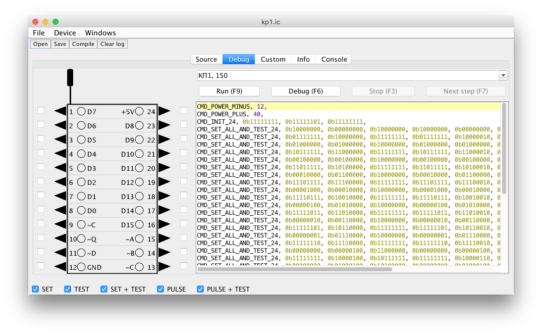
On the menu -> Windows can open one of the three tester windows. "Test builder" is a test editor and debugger. Here you can write, compile, and run tests, performing them step by step.
There is also a manual test mode.
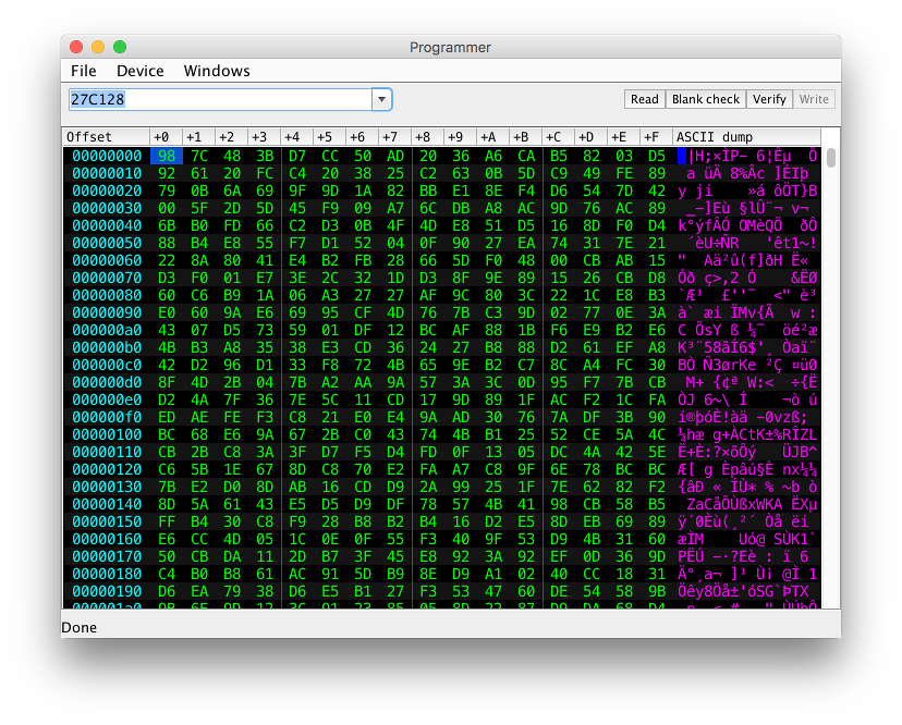
Menu Command -> Windows -> "Programmer" opens the programmer window (so far you can only read the contents of the ROM chips).
Menu Command -> Windows -> "Logic tester" opens the logic chip test window. Here you can run the autotest of logic/analog chips, similar to how it is done in the tester.
Test development
The test writing language is described in detail here (in Russian).
The source codes of some tests can be found here
Files and links
You can purchase the device in the store.
Software:
For devices with firmware v0.9.24 and above
 software.jar
For devices with firmware v0.9.23 and below
software-old-129.jar