Two microcontroller regulators for fans

This device allows to reduce the noise from cooling fan. It turn off the fan or reduces the rotation speed depending on the temperature of the radiator. Also the device beeps when temperature exceeds a threshold. There are two variants of device for fans of different power.
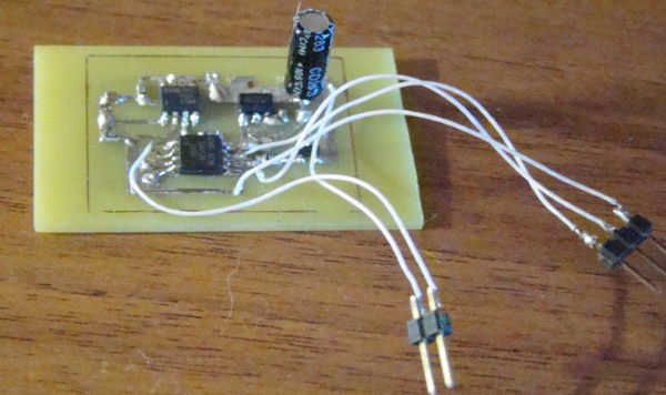
The first variant is designed to control 12-volt computer fan, and has been fully implemented on the SMD-elements:
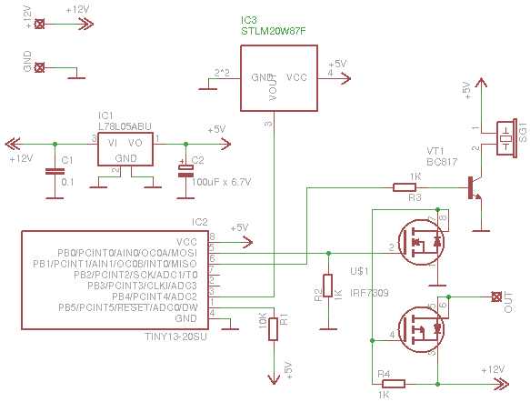
The chip STLM20W87F is analog temperature sensor, value of the voltage at its output is proportional to the temperature (the voltage decreases almost linearly with increasing temperature). This voltage is measured by the ADC of the microcontroller. The voltage on the fan is regulated by PWM, the fan is connected via FET-switch. The beeper makes alarm signal when exceeding the temperature threshold as well as short signal when the device is switched on (this indicates that the controller is working, and is connected).
The second variant is different only to using a Power MOSFET and voltage regulator, as well as the microcontroller in DIP package:
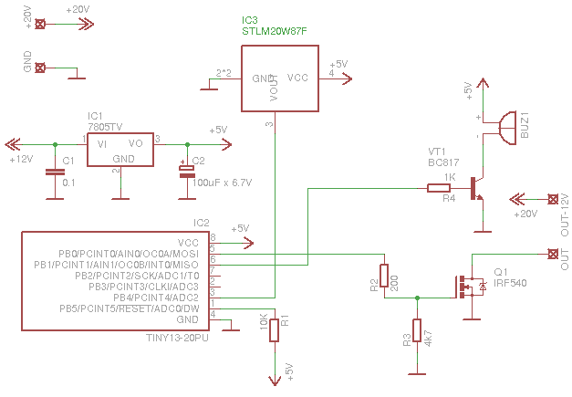
This circuit can control more powerful fans with a supply voltage up to 30V.
Control program for the microcontroller works as follows:
- when the device is turned on it beeps
- the temperature is continuously measured and if it exceeds the first threshold (40 degrees Celsius) the fan is switched on for half power
- if the temperature exceeds the second threshold (45 degrees) the fan will be turned on at full power
- if the sensor begins to cool then the fan switch to half power at achieving intermediate threshold (42 degrees)
- in case of further cooling of the radiator the fan wil be completely turns off when the temperature drops below the first threshold, and will remain so over 50,000 measurements
- if the temperature exceeds a critical threshold (75 degrees), the device will sound an alarm
- the watchdog timer protects the device from freezing
Both schemes use the same firmware. The project is written and compiled with Eclipse + AVR plugin. At the beginning of the source file contains a table to convert the value measured by the ADC value of the temperature in degrees Celsius. Further declared the configuration macroses.
#define FIRST_THRESHOLD_ADC      289   // 40 grad
#define SECOND_THRESHOLD_ADC     277   // 45 grad
#define BACK_SECOND_THRESHOLD    284   // 42 grad
#define BEEPER_TRESHOLD          210   // 75 grad


#define FIRST_THRESHOLD_PWM      180
#define SECOND_THRESHOLD_PWM     255

#define START_BEEP_NUMBER        1
#define START_BEEP_DURATION      20

#define WARNING_BEEP_PERIOD      500

#define BEEPER_AC                0
The values FIRST_THRESHOLD_ADC and SECOND_THRESHOLD_ADC define the first and the second temperature limits (ie, 40 and 45 degrees). If you need to set other temperatures, the values for them in the table at the beginning of the file.
The value BACK_SECOND_THRESHOLD defines the temperature when cooling below that the power will be reduced to half.
The value BEEPER_TRESHOLD defines the critical threshold for alarm.
The values FIRST_THRESHOLD_PWM and SECOND_THRESHOLD_PWM define the PWM values for both thresholds (0 - the fan is completely off, 255 - the fan is turned on at full power).
The value START_BEEP_NUMBER specifies the number of beeps when switched on,
the value START_BEEP_DURATION specifies the duration of each beep and the gap between them in milliseconds.
The value WARNING_BEEP_PERIOD defines the period following the sound of alarms in milliseconds.
In the case of DC-beeper the value of BEEPER_AC should be defined as 0, for AC-beeper it should be 1.
I have used the USBASP programmator with avrdude software for writing the firmware with commandline:
avrdude -c usbasp -pt13 -u -Uflash:w:Release/fantermocontroller.hex:a
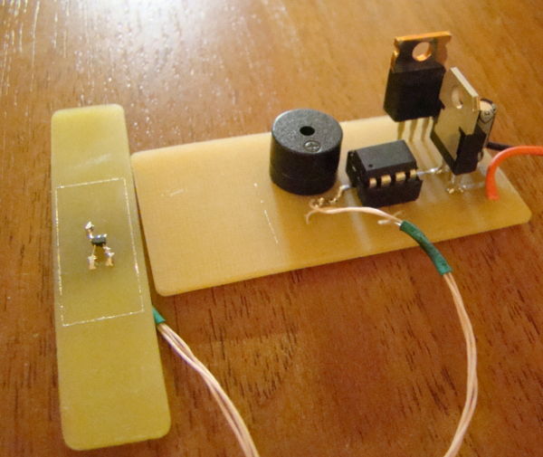
The first circuit is mounted on one PCB, the second contains two boards:
On the links below you can download the circuit, PCB-layout, the source code and firmware. Also attached is a Python script to calculate conversions voltage and temperature readings in the ADC.
Download:
 Circuit and PCB (Eagle + SVG files) Firmware with sources Firmware Script for calculation the table of temperature