Bresenham's line algorithm for power control
When creating a microcontroller devices periodically there is a problem of regulation of some of the analog value, such as voltage at the IC pin, LED brightness, power, etc. In order to form an analog signal with a given amplitude at the pin of chip commonly used method of pulse-width modulation - PWM. The basis of the PWM output is on pin IC pulses with varying duty cycle. The higher the duty cycle D, the higher the amplitude of the signal after passing through a pulse integrating RC-chain:
The advantage of the PWM is the simplicity of its implementation - most modern microcontrollers have hardware support for PWM. But there are situations in which the PWM does not give the desired result - for example, if need to control the brightness of the LED. That's it look PWM diagrams for different brightness:
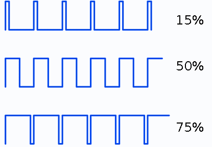
At each iteration, the PWM gives one positive pulse, the duration of which is proportional to the intensity. As a result, the LED will flash quickly. And because the pulses have a relatively high frequency, and our vision is inert, we take it as a continuous glow. Flicker frequency is equal to the frequency of the PWM and in the case of low brightness and not too high frequencies it may be noticeable for eye. And to get rid of it is necessary to increase the PWM frequency, which is not always possible. For example, when you want to control not a single LED but large LCD display with a dynamic indication.
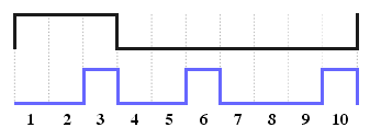
The second way to reduce flicker, a change in the shape of the control voltage. Ie instead of one large pulse should send a series of shorter pulses of the same total length and equally distributed over the entire interval.

But how can we do even distribution of pulses over an interval? Search the web gives the answer - should to use the Bresenham's algorithm. The Bresenham line algorithm is an algorithm which determines which order to form a close approximation to a straight line between two given points.. But how is it related to the problem about equally filling the entire interval with pulses?!
Let's see. Suppose we need to distribute the M pulses (here M=brightness) to N cells. Let's draw a straight line in the Cartesian coordinate system. X-axis we plot the time (0 .. N-1), the Y-axis line will reach the point (N, M) Ie for brightness 100% (M = N) slope angle is 45 degrees.
Grid size:
Slope:
Take a good look at this graph can already see our uniformly distributed impulses. Let us differentiate our line (ie we calculate the difference Y[ i+1 ] - Y[ i ]).
Grid size:
Brightness:
It remains understand the algorithm. Drawing the line is implemented by pseudocode:
function line(x0, x1, y0, y1)
     int deltax := abs(x1 - x0)
     int deltay := abs(y1 - y0)
     int error := 0
     int deltaErr := deltay
     int y := y0
     for x from x0 to x1
         plot(x,y)
         error := error + deltaErr
         if 2 * error >= deltax
             y := y - 1
             error := error - deltax
Adding calculate the difference the previous value, we obtain a diagram of the pulses:
uint8_t bresenham_data[10];

void calcBresenham(uint8_t size, uint8_t brightness) {
  size--;
  brightness--;
  int error = size - brightness;
  uint8_t x = 0;
  uint8_t y = 0;
  uint8_t prevY = 1;
  while ( x <= size ) {
    const int error2 = error * 2;
    bool value = y != prevY;
    bresenham_data[x] = value;
    prevY = y;
    if ( error2 > -brightness ) {
      error -= brightness;
      x++;
    }
    if ( error2< size ) {
      error += size;
      y++;
    }
  }
}
Then this function can be simplified as:
void calcBresenham(uint8_t size, uint8_t brightness) {
  int16_t error = size - brightness;
  uint8_t x;
  for (x = 0; x < size; x++) {
    if ( error < size/2 ) {
      error += size;
      bresenham_data[x] = 1;
    } else {
      bresenham_data[x] = 0;
    }
    error -= brightness;
  }
}
Finally, we can change the algorithm a little more and make it into a library file:
typedef struct bresenham_struct {
  uint8_t size;
  uint8_t value;
  int16_t error;
  uint8_t stepNumber;
} bresenham_struct;

void bresenham_init(struct bresenham_struct *st, uint8_t size) {
  st->size = size;
}

void bresenham_setValue(struct bresenham_struct *st, uint8_t val) {
  st->stepNumber = 0;
  st->value = val;
  st->error = st->size/2;
}

bool bresenham_getNext(struct bresenham_struct *st) {
  bool result;
  st->error -= st->value;
  if ( st->error < 0 ) {
    st->error += st->size;
    result = true;
  } else {
    result = false;
  }
  if ( ++st->stepNumber >= st->size) {
    st->stepNumber = 0;
    st->error = st->size/2;
  }
  return result;
}
Here structure bresenham_struct stores information about the settings and the current state sequence generator Bresenham;
The method bresenham_init(st, size) called at the time of initialization and sets the number of partitions of the time axis (the number of degrees of brightness);
The method bresenham_setValue(st, value) called to set the brightness. For example, if size = 100 then the brightness can be from 0 to 99;
The method bresenham_getNext(st) called periodically by the timer interrupt (or any other way) and returns true if need to generate positive pulse and false otherwise.
The result of the latter algorithm can be seen below:
Grid size:
Brightness:
Click links below to download the file with the implementation of the algorithm (for the AVR GCC) and a file with the test that verifies the validity of generated sequences.
 bres_test.c - tests