The Rat: C-- compiler for AVR
AVR microcontrollers programming practice shows that you can write the most efficient code only in assembler language. But writing assembly code is difficult (and sometimes very difficult). And this complexity is largely due to the primitiveness of assembler compilers, which give too few opportunities for the programmer to write easily readable code. When writing assembly code, there is a desire to have a more convenient syntax, similar to the syntax of C, where you can use familiar and more readable constructs instead of assembler mnemonics. Similar to how it is done in the C-- language. This prompted me to create a language and compiler for the AVR microcontroller, which allows you to write very compact and very fast code. I called this programming language The Rat.
Language syntax
You can look at the Rat compiler as an almost classic assembler language with a C preprocessor. All code can be written in almost "ordinary" assembler. However, there are several features:
- All code must be placed in procedures (
proc) - The processor type must be specified by the directive
#define CPU - Variables are declared with a keyword
var
Let's consider a simple example of a blinking LED code in pure assembler:
#define CPU "atmega8"

proc main() {
  sbi	DDRD, 0
main_loop:
  sbi	PORTD, 0
  ldi	r21, 100
  rcall	delay
  cbi	PORTD, 0
  ldi	r21, 200
  rcall	delay
  rjmp main_loop
}

proc delay(time: r21) {
loop_1:
  ldi r22, 0xff
loop_2:
  nop
  dec	r22
  brne	loop_2
  dec	r21
  brne	loop_1
  ret
}
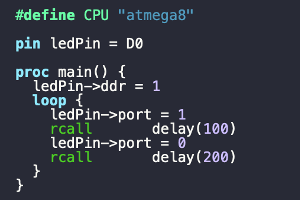
The same code can be written in Rat like this:
#define CPU "atmega8"

pin ledPin = D0

proc main() {
  ledPin->ddr = 1
  loop {
    ledPin->port = 1
    rcall	delay(100)
    ledPin->port = 0
    rcall	delay(200)
  }
}

proc delay(time: r21) {
  loop (time) {
    loop (r22 = 0xff) {
      nop
    }
  }
  ret
}
The number of assembler menmonics has decreased in this code. Also, there are fewer labels in the code (more precisely, they are not left at all). As a result, even such trivial code has become more compact and readable. But the efficiency of the code was not affected.
Procedures
All program code must be in procedures.
Procedure declaration consists of the keyword proc, an optional argument list in parentheses,
and a procedure body in curly braces. All labels declared inside the procedure are local and cannot be seen from the outside.
If you need to declare a global label that is accessible from other procedures, then an ampersand is placed before its name:
@global_label:You can specify a list of arguments for the function. For example:
proc drawCircle(x: r24, y: r22, radius: r20)
Here x, y and radius - are the names of the arguments, r24, r22, r20 -
the names of the registers in which these arguments will be passed.
These argument names can be used in the procedure body as aliases for the corresponding registers.
Also, these names can be passed when calling the function (with directives rcall, rjmp, call and jmp.
For example:
rcall drawCircle (x: 20, y: 30, radius: 15)
The compiler will add the necessary variable initialization instructions before the call rcall.
The initialization order is determined by the order in which the arguments are listed in the invocation command.
For our example, the following code will be generated:
  ldi	r24, 20
  ldi	r22, 30
  ldi	r20, 15
  rcall	drawCircle
As an argument value, you can use not only constants, but also other registers, variables, ports and expressions.
If the procedure has only one argument, then its name can be omitted when called. For example for a procedure
proc delay(time: r21)both rcall options are possible:
  rcall delay(100)
  rcall delay(time: 100)
It is important not to forget that there should usually be a return command at the end of the procedure (ret or reti for interrupt handler).
This command must be written explicitly by the programmer.
Registers and register groups
The AVR has 32 8-bit registers (r0 - r31), and for storage and transmission of large values, they are far from always enough.
Registers can be grouped with a dot. For example:
r24.r23
Here r24 is high byte and r23 is low byte. Example of a group (24-bit) of three registers:
r20.r22.r2Such groups can be used in expressions and as arguments of procedures.
AVR microcontrollers have register pairs that have a special purpose (access to RAM and flash memory).
  X = XH.XL = r27.r26
  Y = YH.YL = r29.r28
  Z = ZH.ZL = r31.r30
You can use all of these names in your code. It should be noted that r-register names are not case-sensitive ("R" or "r").
But the names of register pairs and their components ( X , XH , XL , etc.) are written only in capital letters.
In general, all identifiers in the language are case-sensitive (as in C), except for r-register names and assembly instructions (as in assembler).
Aliases
Aliases allow you to assign a readable name to a register or register group. An alias is declared using the keywords use as.
For example:
  use r23 as flags
  use r10.r11.r12 as counter
Aliases can be both global and local. Global aliases are declared outside of procedures and are available throughout entire program. Local aliases will only be available in the procedure where they are declared.
Local aliases (along with named arguments) solve one of the problems of assembly language - the need to keep in mind the purpose of all registers when working with code.
If the register is used only as a global variable, then when declaring an alias, you can "capture" it by specifying an exclamation mark at the end:
use r0 as reg_zero!
Such a code prohibits reference in the code to the register r0 by its "machine" name, access will be possible only by an alias.
Capturing the register allows you to prevent its erroneous use in case you have forgotten somewhere that the register is used as a global variable
and try to use it as a general (temporary) register, forgetting to save/restore the contents after use.
Variables and arrays
In addition to registers, non-constant program data can also be stored in RAM (SRAM). Variables and arrays are used to address RAM.
Variables are declared using a keyword var and can be of the following types:
byte, word, dword - memory cell of 1, 2 and 4 bytes, respectively.
ptr - pointer, SRAM address (2 bytes)
prgptr - pointer, flash memory (PRG) address (2 bytes, flash memory is addressed in two-byte words).
Variable declaration examples
  var current_command: byte
  var a1, a2, a3: byte
  var backlight_time: word
In addition to simple variables, you can declare an array by specifying its size in square brackets:
var video_memory: byte[32]
IO-ports
To access the ports, their names are used, which are loaded from the dev-file of the microcontroller. The dev file also describes the names of the bit fields for I/O ports. I/O ports can be accessed like ordinary variables to write and read them:
  r24 = ADC
  ADCSRA = r24
you can also write and read their bit fields (both by the bit number and by its name):
  ADMUX->0 = 0
  ADMUX->MUX0 = 1
Likewise, port bit-fields can be used in conditions and loops:
  if (!ADMUX->0)
  if (ADMUX->MUX0)
  loop (!SPSR->SPIF) {}
Preprocessor
The built-in proprocessor is similar to the C preprocessor and supports the following directives:
#include, #define, #undef, #ifdef, #ifndef, #if, #else, #elif, #endifComments
Single line and multiline block comments are supported. One-line comments have traditional assembly syntax and begin with a semicolon:
var rx_buf[32] ; UART read buffer
For block comments, C-style is used (/* */):
  /*
     Any text
     before
     the closing brackets
  */
Interrupts
To declare the interrupt vector table, a block vectors, consisting of interrupt labels and their handler code is used.
The interrupt names of a specific microcontroller can be viewed in its .dev file.
The handler command must be exactly one word long.
The default block contains a command that will be written for all interrupts by default (usually reti).
The default block is optional.
Example:
  ; interrupt vector table declaration
  vectors {
    TIMER2_COMP:
      rjmp   timer2_comp

    default:
      reti
  }

  ; interrupt handler declaration
  proc timer2_comp() {
    reti
  }
$org directive
If you need to place a block at a specific flash memory address, use the $org(address) directive.
Where address is the address (even!) in bytes at which the procedure will be located in the microcontroller program memory.
This directive is useful primarily for writing bootloaders.
Example:
  #define BOOT_START			0x1f00

  $org(BOOT_START)
  proc init_bootloader() {
  }
Extended syntax (aka C--)
In addition to assembly instructions, more human-readable variants from C-like languages can be used.
Expressions
A register (or group) can be assigned some expression from the sum or difference of other registers (groups), constants, variables and ports. Some examples:
  r1 = r2            ; copy registers
  r24 = 010          ; writing octal value to register
  r24 += '0'         ; addition register with character constant (ASCII character code)
  r24 = r25 + 0x12   ; addition register with hexadecimal value
  r24 &= 0b10100000  ; logical AND register with binary value
  r1 = -r2
  r1 = r2 + r3 - 8
  r1 = -r2
  r1 += r2
  r1.r2++            ; register pair increment
  r1.r2 += 1000      ; addition register pair with constant
  r1.r2 = X + 10
  r1 = byte_variable + 10          ; initializing the register from SRAM variable with adding 10
  r25.r24 = word_variable - 1      ; initializing the register from SRAM variable with decrement
There are limitations and not every construct can be compiled. But the principle is that if some expression can be translated into assembler in the most efficient way, then the compiler will compile the code. If this is not possible (for example, without using auxiliary registers or stack), then it will throw an error. For example, it will not be possible to assign a register the sum of the values of two SRAM-variables, since such an operation would require the use of an auxiliary temporary register.
At the same time, the compiler generates the most efficient code.
For example, when compiling expressions with register pairs, the instructions
будут использоваться инструкции movw, adiw and sbiw will be used.
Expressions can use multiple assignments, which is convenient when writing to ports.
For example, initializing the stack pointer with the constant RAMEND using auxiliary registers might look like this:
SP = r16.r17 = RAMENDor like this:
  SPH = r16 = high(RAMEND)
  SPL = r16 = low(RAMEND)
Multiple assignments are performed from right to left. That is, for the given examples, the constant will be written to the register first, then this register will be written to the port.
The language allows you to access register bits directly as array elements:
r21[0] = 1Conditions
The conditional operator if - else is similar to that in C-like languages.
Expressions that operate on registers and groups (arithmetic comparison, operations ==, !=, <,>, <=, >=), as well as bits of registers and I/O ports can be used as a condition. Examples of conditions:
  if (r10[5])        ; register bit check
  if (!ADMUX->0)     ; I/O port bit check
  if (ADMUX->MUX0)   ; I/O port bit check
  if (r21 == 0xFE)   ; checking case equality to a constant
  if (r21.r22 < ZH.ZL) ; comparison of two register pairs
  if (SREG->Z) ; SREG bit check
Also supported complex expressions (using operators && ||, ! and round brackets).
The body of an operator can be either one command or a block in curly braces.
By default, all comparisons are unsigned.
To compare some register with signed value, use the (signed) transformation for a signed-value register.
For example:
  if ((signed)r12 >= -50)
  if (((signed)r12 >= -50) && ((signed)r12 <= -3))
Cycles
The loop keyword is used to declare loops. The argument can be an expression with a register-counter (or a register pair)
  loop (r24 = 123) {
      nop   ; the body of the loop will be executed 123 times until r24 reaches zero
  }
The right-hand side of the expression can be omitted (if the required initialization has already been done before):
  loop (r25.r24) {
      nop
  }
Also, the loop argument can be bit of I/O port:
  loop (SPSR->SPIF) {}    ; waiting for setting SPSR->SPIF to 0
  loop (!SPSR->SPIF) {}   ; waiting for setting SPSR->SPIF to 1
You can also create an endless loop:
  loop {
   ; endless loop
  }
You can use the break and continue statements in the body of loop.
The first one interrupts the execution of the loop, the second one - the transition to its beginning
(i.e., to checking the condition and executing the next iteration, if it is executed).
mem[] and prg[] arrays
The keywords mem and prg allow you to access the microcontroller's RAM
(for reading and writing) and its program flash memory (for reading), respectively.
Reading from the mem[] array is translated into instructions ld and ldd.
Writing to the mem[] array is translated into instructions st and std.
As array index mem[] can be used any register pair: X, Y,
Z. Increment and decrement are possible here (prefix and postfix)
In case of indexing by the Y pair it's also possible to specify an offset
Y+q, где 0 ≤ q ≤ 63 (see instructions ldd and std).
Examples of using mem[] array:
  ; read indirect memory location
  r24 = mem[Z]

  ; filling the array with zeros
  r16 = 0
  loop (r17 = 32) {
      mem[Z++] = r16
  }

  ; reading from UART to memory array
  loop (r23 = PAGE_SIZE) {
      rcall uartWaitChar
      mem[Y++] = r24
  }
The quasi-array prg[] gives read-only access to flash memory data.
Reading from the array prg> is equivalent to using the lpm instruction.
Here the index can only be Z or Z++.
For example:
; reading an array from the code area to SRAM (using an intermediate register)
loop (r16 = 15) {
    mem[X++] = r0 = prg[Z++]
}
Working with IO-pins
The keyword pin describes a single pin of some I/O port, allowing it to be referenced by name.
The pin declaration looks like this:
  pin pinLcdE    = B5
  pin pinKeyLeft = C1
These declarations mean that the pin number 5 of port B gets the alias name pinLcdE, and pin 1 of port C is the alias name pinKeyLeft.
Three attributes are available for pins: port, ddr and pin,
which allow accessing the corresponding bits of the ports PORTx, DDRx and
PINx as follows:
  pinLcdE->ddr = 1               ; set pin pinLcdE to output
  pinKeyLeft->ddr = 0            ; set pin pinKeyLeft to input
  pinLcdE->port = 1              ; set high level for output pin
  pinKeyLeft->port = 1           ; enable pull-up for input pin
  if (pinKeyLeft->pin) r24 = 0   ; checking the level of input pin
Pins can also be used as an index to access register bits.
  r16 = PORTB
  r16[pinLcdRs] = 1
  r16 |= 0b11100000
  PORTB = r16
high(), low(), bitmask() and sizeof() operators
Operators high() and low() take one double-byte argument and return its high / low bytes,
respectively.
For example:
  UBRRH = r16 = high(UART_UBRR)
  UBRRL = r16 = low(UART_UBRR)
The sizeof() operator takes one argument (SRAM variable or array) and returns its size:
  var video_memory: byte[32]

  ; ....
  loop (r20 = sizeof(video_memory)) {
    ; ...
  }
The bitmask() operator takes a variable number of arguments (1 to 8) with bit numbers (0 to 7) and
produces a bitmask based on them. The arguments can be constants, bits of I/O ports, or pins.
It doesn't sound clear, and it is better to look at examples:
  ; these two expressions are equivalent
  r24 = (1 << PGWRT) | (1 << SPMEN)
  r24 = bitmask(PGWRT, SPMEN)
In addition to being compact, the advantage of using bitmask() operator is that the compiler will
check that all bits belong to the same I/O register, and will generate an error
if dissimilar bits combination (if arguments belonging to different ports).
Here are some more examples of using bitmask():
  UCSRB = r16 = bitmask(RXEN, TXEN)
  UCSRC = r16 = bitmask(URSEL, UCSZ0, UCSZ1)

  pin pinLcdE   = B5
  pin pinLcdRs  = B4
  DDRB = r16 = 0x0F | bitmask(pinLcdE, pinLcdRs)
Inline-procedures
Inline procedures are analogous to assembly macros, when "called" in the code, the contents of the procedure body will be inserted at the place of the call. It makes sense to use them instead of short (1-3 instructions) procedures, or instead of procedures called only once, to better structure the code. Example:
  pin highlight = A7

  inline proc highlight_enable() {
    highlight->port = 0
  }

  inline proc highlight_disable() {
    highlight->port = 1
  }

  ; .....

  highlight_disable()
Using Rat with AVR GCC
The Rat compiler can generate both ready-made machine code (in hex or binary format) as well as an assembly listing in AVR GCC format (S-file). The first mode allows you to write all the code entirely in Rat, the second mode allows you to use Rat together with C (to write only critical sections of the code on Rat).
When used together with the C language, two questions arise: "how to call Rat procedures from the C code?" and "how to call C procedures from Rat code?".
The Rat compiler generates an assembly listing by declaring all procedures as global, which makes them available in C code
(where they must be declared as extern ).
To access C procedures and variables from Rat, you must also use the extern directive when declaring a function or variable:
  extern proc readNextByte()
  extern proc writeNextByte(b: r24)
  extern var buffer: byte
To use Rat procedures and variables from the C code, they must be declared in the standard way
  uint8_t readNext();
  void writeNextByte(uint8_t b);
  extern uint8_t buffer;
Compiler and development environment
You can download the compiler from the link at the end of this page. It is written in Java (more precisely, Kotlin) and is cross-platform.
To run under *nix systems, the archive has a shell file ratc. The syntax for starting the compiler is as follows:
Usage: ratc [options] <source_file> [<output_file>]

  OPTIONS:
    -D<macro>=<value>      Define <macro> to <value> (or 1 if <value> omitted)
    -I<dir>                Add directory to include search path
    -dev=<path>            Set path to dev-files
    -gcc                   Produce GCC Assembler file
    -help                  Show this usage screen
The package contains a subdirectory devices with files that describe microcontrollers (sizes of flash memory, SRAM and EEPROM,
interrupt vectors and I/O ports). The #define CPU directive selects the name of the .dev file.
As a result of compilation, .hex and .map files are created by default. The command line option -gcc forces the compiler to
generate assembler code for GCC.
As a development environment, I personally use NetBeans 8.2 (this is the latest Netbeans IDE to support C/C++).
When using Rat and C code together, the project can be built using avr-builder.
Rat source files have the extension .art (Avr RaT) and avr-builder will call the compiler and linker for them.
As one of the examples in the samples directory there is a firmware quartz frequency meter-tester on Atmega8,
rewritten to Rat.
Also in the archive with the compiler there is a plugin for syntax highlighting in NetBeans (/misc/netbeans/ru-trolsoft-therat-avr.nbm).
The source code available on github: https://github.com/trol73/the-rat-avr
Files
 rat-v0.1.tar.bz2 rat-v0.2.tar.bz2 the-rat.jar (nightly builds)